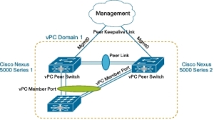
As many may know Virtual PortChannels (or vPC for short) are used widely when it comes to Datacenter designs and Cisco Nexus. It can be compared to VSS on the Catalyst 6500 or 4500-E (or-X) platforms, but are in fact slightly different. Where VSS combines 2 physical switches into one logical switch, Cisco Nexus will combine several links or port-channels into one logical trunk. The Nexus hardware platform will not be logicalized (if that’s even a word).
vPC knows a few mechanisms to ensure correct operation of the vPC domain. One of the is the vPC Consistency check. A very imp0rnant feature for people who think configuring a vPC is a no-brainer, people like me.
So vPC can combine several links or several port-channels into one logical trunk link crossing the hardware boundary (like multi-chassis ether channels). What happens when you receive seemingly L1 or L2 issues on the links who participate in a vPC. Especially when your doing expansions in your network. See the below output:
NX5K-DSW1# sh int eth1/18
Ethernet1/18 is down (Type1Incompatibility)
  Hardware: 10000 Ethernet, address: 0005.73b5.6f99 (bia 0005.73b5.6f99)
  Description: TRUNK TO NX4K-ASW1 E1/15 vPC16
  MTU 1500 bytes, BW 10000000 Kbit, DLY 10 usec,
     reliability 255/255, txload 1/255, rxload 1/255
  Encapsulation ARPA
  Port mode is trunk
  auto-duplex, 10 Gb/s, media type is 10G
  Beacon is turned off
  Input flow-control is off, output flow-control is off
  Rate mode is dedicated
  Switchport monitor is off
  EtherType is 0x8100
  Last link flapped 15:13:21
  Last clearing of "show interface" counters never
  30 seconds input rate 0 bits/sec, 0 bytes/sec, 0 packets/sec
  30 seconds output rate 0 bits/sec, 0 bytes/sec, 0 packets/sec
  Load-Interval #2: 5 minute (300 seconds)
    input rate 0 bps, 0 pps; output rate 0 bps, 0 pps
  RX
    0 unicast packets  0 multicast packets  0 broadcast packets
    0 input packets  0 bytes
    0 jumbo packets  0 storm suppression packets
    0 runts  0 giants  0 CRC  0 no buffer
    0 input error  0 short frame  0 overrun   0 underrun  0 ignored
    0 watchdog  0 bad etype drop  0 bad proto drop  0 if down drop
    0 input with dribble  0 input discard
    0 Rx pause
  TX
    0 unicast packets  12 multicast packets  0 broadcast packets
    12 output packets  2727 bytes
    0 jumbo packets
    0 output errors  0 collision  0 deferred  0 late collision
    0 lost carrier  0 no carrier  0 babble
    0 Tx pause
  0 interface resets
With no special knowledge on how vPC operate you would likely guess there is a twinax or glassfiber SFP incompatability refering to type1 as something that belongs to the fibre vendor that is used in the SFP module. Makes absolutely no sense when using copper twinax 😦
Please note that configuring vPC must happen identically on all the switches that participate for this specific vPC. Misconfiguration can happen easily and because of the various checks the vPC will not go to the status UP. Please check the link below how to check and possibly resolve several issues concerning vPC.
In the case mentioned above everything was configured correctly on DSW1, but the vPC statement on the corresponding interface on DSW2 was missing resulting in the stated error above in red and the link that failed to go to UP status. When troubleshooting vPC try to see the complete vPC as one whole and check every switch within that domain. An error seen on DSW1 doesn’t mean that DSW1 is having the issue.
Virtual Port Channel Operations
Pay special attention to chapter: Type 1 and Type 2 Consistency Check Parameters


